")
")


Boran Automation Systems
Boran Software
-
Automation Systems with PLC
General advantages of PLCs are as follows. There is a protection system against almost all hazards.They occupy very little space according to the functions and abilities they perform.Although the initial investment costs are high, it is a system that pays off in the following years.It is very durable. As it is industrial production, it is resistant to impact, dusting, overheating.
PLC devices can also communicate with each other and with other communication devices.For example, they may be in constant communication with their computer or mobile phone.PLCs can control many devices and machines at the same time.They also have the capacity to process very quickly.They perform logical and arithmetic operations in seconds.Another feature that can be counted as one of its biggest features is its ability to scan faults and to check past working situations.
-
HMI Systems
With the advancement of technology, the automation sector gains more value and tries to produce more innovations in order to catch up with the technology. HMI Systems are also the basis of these production stages. The term HMI, known as "Human-Machine Interface", has become the favorite of the "Industrial Automation" sector with the names such as "touch panel", "touch panel", "operator panel". It is known as the unit that provides interaction between the automation system realized by using PLC (Programmable Logic controller, Programmable Controller) systems and the user. In short, we can say that the future of the sector is in the hands of HMI technology.
HMI can also be called a device or software assembly that allows the user to communicate with machinery and manufacturing facilities. So how does it do this? By translating complex data within an accessible information, the operator controls the production process. If we are to express its basic duty more clearly; It transmits the orders received from the operator to the automation system and displays the process data received from the automation system on the screen. Depending on the scale of the automation system, data can be displayed on several pages, as well as a complex structure consisting of dozens of main and sub-pages. HMI has the hardware to handle all these events.
We considered MI Systems as a general concept. The basic tools that make up the system are HMI Panels. What do these panels contain? Basically, the HMI device provides visualization and application control. Thus I / O, EtherCAT and (embedded "embedded" systems in SoftPLC CoDeSys are more preferred). It was developed as microcomputers running an operating system on HMI Panels. In general, operating systems are closed to the user and they are programmed with the help of special editors. In addition, Windows, Linux, etc., also referred to as an industrial computer. Powerful systems with an operating system can also be used. RS232, RS485 or Ethernet connection can be used for communication between panel and PLC. Each brand supports one or more types of connections in their products. Generally HMI panels can also communicate with PLCs of different brands. For this operation, the device must be configured as specified by the manufacturer.
In the Industrial Automation sector, there are different models of HMI than devices with a large 4.3 ”screen and a 15.6 inch screen. In this way, everyone can reach the solution they want and need. As a result, it can be clearly stated that the HMI system is more responsive and user-friendly and is a more efficient and cost-effective tool.The evolution of HMI
To fully understand what the concept of HMI is, we must take a step back. In fact, we should start with zero and see how your technology has evolved: it all started with a button. And then light was added. Lighted buttons came next. Later, wired devices with electronic panels appeared. Finally, it's time for personal computers and software programs to conquer the scene with even more sophistication. And so, in a few years, the world of Human-Machine Interfaces has evolved greatly. Nevertheless, experts have no idea yet about the invisible part of the iceberg beyond the tip of the iceberg ... But what do these systems do with their unlimited potential? There are two answers: Software; We are witnessing that previously assumed options (touch screen or color screen etc.) are included in a progressive standardization today, and companies have come to compete in terms of software and SCADA. Integration with new "physical" technologies; is the trend of common use with technological devices. This is the trend for the latest generation HMIs. This ensures that HMI products are easy-to-use and user-friendly on people's smartphones and tablets and similar platforms.
HMI in Industrial Automation industry
Finally, the most interesting part for those working in this industry comes. What is the relationship between Industrial Automation and HMI? Basically, the HMI device provides visualization and application control. This allows I / O to communicate with any production facility using resources in SoftPLC CoDeSys or operating systems such as EtherCAT and (embedded "embedded" systems are more preferred). Depending on the facility, you can change the device's features in terms of connectivity, technology and even dimensions. Therefore, in the Industrial Automation industry, you can find different models of HMI from devices with a standard 4.3 ”screen and a wide screen with a 15.6 inch screen. In this way, everyone can reach the solution they want and need.
What is the working environment where your HMI will be used?
The environmental conditions in which the HMI will operate is one of the most important factors affecting the HMI selection. Any non-standard work environment will reduce your HMI options. For example, an environment where electrical noise or vibration is intense enforces the choice of a panel that is more solidified and has a higher protection level. Or the HMI to be used in washing facilities such as the food process must have a high IP protection class. Or an HMI to be used close to the furnace will need to withstand high temperatures. It should be noted that the texts on the screen of an HMI to be used in the external environment can be read even in daylight.
What are the user's requests and implementation?
We cannot always expect the user to know and define all their needs at the beginning of the project. Therefore, it is useful to predict reserve capacity when choosing HMI. In other words, you should select the memory and its features such as I / O capacity (if any) slightly larger than expected at the beginning of the project. Although there are many HMI applications, we can basically collect the applications in 3 categories.
As pushbutton: Without HMIs, the machines were operated with push buttons and selector switches. Process information was followed by indicator lamps and digital indicators. Buttons and indicators have been moved to the HMI screen in most applications today.At this point, it is necessary to pay attention to the size of the screen while making the selection. Whether the user wants to see all the buttons on the same screen, or whether each button will be on separate screens, will significantly affect the HMI screen size.
Data Processor: Prescriptions, data graphics, reports, alarms are features that the operator should follow or use in some applications. An intermediate HMI in facilities producing more than one different may include these features. Probably a 6 inch color graphic display can show this data and graphics. Saving data is a criterion that affects the memory selection of the HMI - in this case, the HMI with a memory of at least 4-6 MB can be selected. This time, communication options come to the fore as the data will also need to be transferred to the HMI and another medium from the HMI. Whether data transfer is automatic or manual is also an important factor affecting this choice. If it is to be automatic, you should choose an HMI that has an Ethernet or Serial port and supports the required protocols. If manual data transfer is accepted for the user, a flash card feature will be sufficient. Some HMIs only support KSV, CSV or binary format as data file. The answer to this question will also affect your HMI selection.Tracing: Is there an MES system or SCADA that requires an interface with database operations, data warehouse and enterprise software in the application? With its current success and low cost on real-time data analysis, an appropriate HMI can add significant value to such applications.
-
Scada System
SCADA created with the first letters of the words Supervisory Control And Data Acquisition; It is called the "Central Supervision Control and Data Collection" system. SCADA systems are a system where wide-spread facilities can be monitored from a single center with devices such as computers, mobile phones or tablets, and they are basically software. It can be used from a single device as well as control and monitoring with multiple computers and portable devices with network connections.
Main Features of SCADA Systems
► Graphical Interface
► Monitoring System
► Alarm System
► Data Collection, Analysis and Reporting Systems.
SCADA consists of three basic parts;
► Remote Terminal Unit (RTU)
► Communication System
► Control Center System (Main Control Center AKM - Master Terminal Unit MTU)
Communication Protocols
Many devices used in industrial applications use EIA standards RS-232, RS-422 and RS-485 to connect to computers or each other.
Control Units
Main PLC, auxiliary PLCs, electronic protection and locking systems, motor control units are the main control units. Main PLC, which is the most important part, keeps the whole system under control. Therefore, it should have certain features. These features;
► It must be able to talk to more than one master station simultaneously on separate communication channels.
► RS-232 must be able to communicate with multiple protocols on RS-485 physical communication layer, copper and fiber optic physical environments.
► It should have the ability to be easily expanded, configured and maintained.
► It should be able to make its own tests and have a structure that warns the malfunctions both on itself and the SCADA center.
► When replacing a defective module, there must be a hardware structure that does not require power off.
As an example of the most used SCADA software; WinCC, Citect, ICONICS, iFIX, Indusoft, Entivity Studio.
The basic logic of SCADA is to observe and control all production stages from a single center, to collect-report data and to control units. It has a large usage area due to these features it provides.
Usage Areas of SCADA
► Nuclear Facilities
► Electric Facilities
► Water Collection-Treatment-Distribution Facilities
► Traffic Control Systems
► Automotive Industry
► Natural Gas Facilities
► Food Industry etc.
Although the initial costs seem high, the advantages listed below allow the system to pay for itself in a short time
SCADA Advantages
► The system can be monitored at any time
► Time and labor savings
► Ability to record and analyze production data
► Energy monitoring and saving of the system
► Prevention of penalty situations (Compensation etc.)
► Getting news from the situation in the field and immediate response
► Recording of interventions made to the system
► To be able to identify regions with a risk of failure
► It has great advantages such as getting instant information about the operation of the system (switch status etc.).
-
Servo Motor and Servo Motor Drivers
Servo motor acts as the final control element in a mechanism by executing the commands of the operator. These commands can be position and velocity commands or a combination of velocity and position. Servo motor needed a driver to execute commands
1) DC Servo Driver
They are drivers working with direct current. They are analog or digital drives that work with pulse width modulation (PWM). Feedback is made with an incremental encoder or tacho generator. It is an inexpensive and easy-to-use driver system.
2) AC Servo Driver They work with alternating current. They are analog or digital drivers that work with sinusoidal pulse width modulation. Feedback is made with a Hall sensor or analyzer incremental encoder. AC servo drives, whose use requires knowledge, have higher performance than DC drives and are more expensive than DC drives.
Selection of Feedback Elements
The driver transmits the information sent to him to the engine. The suitability of the position is checked by the feedback elements whether the speed is correct or not. Information that feedback elements send as feedback:
► Resolver or Sin-Cos encoder
► Absolute position measurement requirement
► Incremental encoder high speed operation
► Resolver or encoder low speed operation
► Incremental encoder Accuracy (sensitivity)
listed as.
Resolver
► Used for position measurement
► Measures position directly when the system is energized
► Suitable for high temperature operation
Incremental encoder
► Speed and position control with high resolution
► Noise free
► Long distance operation with RS422 intermediate circuit
► 100 °C maximum operating temperature
Sin-Cos encoder
► Absolute value measurement
► Measures position directly when the system is energized
►100 °C maximum operating temperature
Servo Driver Selection
Companies that manufacture servo motors and drivers offer various options to users. They have developed separate drivers for the users to use the motors easily and separate software for these drivers. After selecting the servo motors to be used in the system, the appropriate servo driver and software are selected.
Driver Communication Protocols
Servo drives have become smarter with the advancement of technology. Moving beyond the basic control functions such as torque, speed and position in open and closed loop, it has become a smart module that enables users to commission the system, provide operation and maintenance facilities, and communicate with other systems.
Profibus, interbus, fieldbus and CAN are communication techniques used in the industrial field. Each manufacturer uses its own specific protocols. Protocol differences between companies prevent the communication of different types of drivers used in a facility. This situation has revealed the communication requirement of different protocols.
Communication of different protocols is done by protocol conversion. It is realized with the "BRIDGE" functioning on the second floor of the ISO / OSI layered structure, one of the interconnection elements. Electronic elements are used in bridge design. With the bridge design transferred to FPGA technology, devices become smaller, the risks during failure and assembly are reduced, and system performance increases significantly.
There can be multiple drives on the production line. Drivers must work in harmony with each other. For each information sent, serial communication is used instead of running a line (parallel communication). This is called serial communication. It is more economical than parallel communication.
In some systems, drivers do not need to communicate. It consists of a drive (master) and its auxiliary units (slaves) used to transmit the input and output data from the first different station to the center. This structure is called BUS system.
Today, there is a BUS system produced by many companies manufacturing in the field of automation. The main features that distinguish these systems from each other are:
► The way data and control lines are connected (tree, topology, etc.)
► Data transmission rate and error-free data transmission
► Sensor, feedback gb. Elements are hot-swappable -
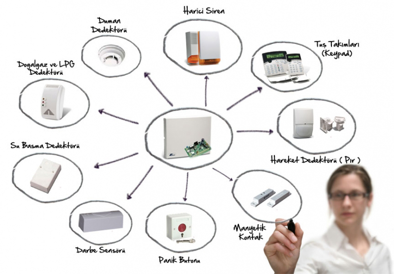
Endüstriyel Güvenlik Çözümleri
-
RFID Teknolojisi
RFID: Radio Frequency Identification: Radyo Frekanslı Tanımlama
Radyo Dalgaları kullanarak taşınan verinin kontrolü sağlanmış çalışma ortamında bilgiye dönüşmesidir.
RFID Teknolojisi canlı ya da cansız tüm nesnelerin takibinde kullanılabilir.
İkinci dünya savaşında radar teknolojisi ile kullanılmaya başlayan teknoloji bugün saniyede 1000 ve üzeri etiket okuyabilen, 100 lerce metre uzaktan algılama yapabilen ve içinde 1000 lerce karakter hafızalı bilgi alabilen çiplerle çalışır hale gelmiştir.
UHF PASİF RFID SİSTEMİ NASIL ÇALIŞIR
RFID okuyucuyu kontrol eden PC okuyucuya ‘etiketi oku’ komutunu gönderir okuyucu anten kablosu ile antene bağlıdır ve antenin etikete radyo sinyalleri göndermesini sağlar.Pasif durumdaki etiket sinyalleri alınca aktif hale gelir ve çipindeki datayı geri yansıtır. Geri yansıyan sinyaller anten tarafından yakalanır, okuyucuya iletir ve PC de bilgi olarak kullanılır.
RFID İş Çözümleri
ÜRETİM TAKİP SİSTEMİ
Üretim yapan tüm işletmelerde, fabrikalarda sahadan bilgi toplamak;
Üretim planlaması maliyet hesaplaması personelin doğru ve verimli kullanılması kaynakların doğru yönetilmesigibi birçok konuda işletmeye avantaj sağlamaktadır.
RFID etiketleri ile fabrika alanında ya da üretimin herhangi bir anında bir ürün ya da personelin hangi konumda olduğu, hangi konumladan ne zaman geçtiği, ne kadar zaman aynı konumda kaldığı bilgileri toplanabilir. Bu bilgiler karar destek yazılımlarına gönderilerek yöneticilerin zamanlarını daha verimli kullanmasını sağlar.
-
Pano Montajı
Pano pano malzeme dökümü çıkarılmış projemizin üretime yönelik iç dış görünüşleri kumandası ve tekhatları çizilir. Müşteri onayı alındıktan sonra elektromontaj aşamasına geçilir.
Tüm şalt komponentlerinin montajı tamamlandıktan sonra projesine ve şartnamesine uygun olarak kablajlama ve %99,9 saflıkta elektrolitik bakır ile akım yolları oluşturulur.
Yine proje ve şartnamesine uygun olarak varsa formlama parçaları, aydınlatma ve havalandırma tertibatı, kablo kanalları ve makaronlar montajlanır.
Montajın en son aşamasında tüm cihaz ve kabloların uygun adresleme ve yönlendirmeler ile etiketlemesi tamamlanır.
-
Elektrik Proje
1) Etüt-öneri raporu:
Projelendirilecek yapının veya tesisin işletme fonksiyonlarını sağlayacak sistemler seçilerek ayrıntılı bir şekilde anlatılır. Projelendirilecek sistemlerle ilgili alternatif çözümler, enerjinin nereden ne şekilde sağlanacağı belirtilerek yapılabilirlik ve ekonomiklik açısından etüt edilir.2) Ön proje:
İşletme fonksiyonlarına uygun olan gerilim dağıtım sisteminin proje üzerinde gösterilmesi, panoların yerleşimi, tahmini güç ve aydınlatma hesapları ve örnek tekhat şemaları hazırlanır.3) Kesin proje:
Elektrik tesislerinin ön projede belirlenen sistemlere uygun nitelikte nasıl yapılacağını detaylı olarak tarif eden açıklama, çizimler, teknik özellikler, hesaplar ve şartnameler ile tamamlayıcı dokümanlardan oluşur, Kesin projeler belirli bir markaya göre yapılmaz, en yaygın kullanılan sistemler göz önünde tutulur.4) Uygulama Projesi:
(Yapım çizimleri ve hesapları) Tesisin yapımına başlanmadan önce, imalatçı firmaların seçilen cihazlarının tip ve ölçüleri kullanılarak hazırlanan projelerdir. Elektrik iç tesislerinde kullanılacak seçilmiş cihazların son yerleşimi ve kesin boyutlandırılması ancak bu hesaplar ve çizimlerle mümkün olur.5) Son durum (yapıldı) projesi:
İmalat ve montajı tamamlanarak işletmeye alınma aşamasına gelmiş olan ve elektrik tesislerinin tamamlanmış durumunu gösteren projedr. Bu proje uygulama projesi (yapım çizimleri ve hesapları) esas alınarak hazırlanır. Projelendirilen tesislerle ilgili işletme ve bakım kitapçıkları bu projelerin ekidir.Taahhüt
Taahhüt işleri konularında başarıyı yakalayabilmek ve uzun süreli başarı elde edebilmek için, kaliteli malzeme ve hizmet, nitelikli personel ile ekip ruhuyla sistemli çalışma gerekmektedir.